Making an Inverted Pendulum using LEGO MINDSTORMS EV3
Introduction
An inverted pendulum is a physical mechanism which contains a rod attached to a cart. The rod is connected to this cart only by a hinge, allowing it to move freely in one-dimension. By moving forwards and backwards with the right acceleration for the right duration, the objective of the cart is to balance the free-moving rod vertically. Constructing such a mechanical system requires both of the following:
- A physical, programmable cart equipped with the necessary sensors and motors
- The usage of control theory to move the cart based on the sensor input
In order to build an inverted pendulum, this research project utilizes a LEGO MINDSTORMS EV3 Kit. Such a kit includes motors, sensors, and a programmable “brick” which can be used to control and receive information.
Significance
The inverted pendulum bears considerable significance for the field of control theory, serving as a transition between theory and practical application [1]. The mechanical system is described as “one of the most fundamental problems in the theory of systems and control,” allowing researchers to test control methodology and implement balancing systems in motion-based technology such as drones [1], Segway [13], and rockets.
The Physical System
Building the physical cart and rod itself was a challenge, accompanied by several setbacks and revelations. The construction of such a system involved the usage and attempted usage of several LEGO MINDSTORMS EV3 components:
Physical Components
EV3 Intelligent Brick [2]
An intelligent brick which contains the accompanying LEGO EV3 Mindstorms software used for programming
- Arm 9 + Linux OS
- Four input ports with sampling rate of 1000 samples/sec
- Four output ports (motor control)
Large Motor [3]
LEGO’s most powerful servo motor
- One degree of accuracy
- 160–170 RPM
- Running torque* of 20 N cm
- Stalling torque** of 40 N cm
Medium Motor [4]
A “lower-load” servo motor with faster response time than the large motor

- One degree of accuracy
- 240–250 RPM
- Running torque* of 8 N cm
- Staling torque** of 12 N cm
Gyroscopic Sensor [5]
Measures rotational motion, both angle and angular velocity in one plane
- 3 degrees of accuracy
- Maximum angular velocity reading of 440 degrees/second
- 1 kHz sampling rate
Multi-functional MindSensor [6]
A third-party component that includes an accelerometer and gyroscope

- Accelerometer accuracy within 10 milli-g
- Gyroscopic rate accuracy within 8.75 milli-degrees/sec
- Used to measure acceleration of cart
EV3 Cables [7]
Used to connect the motors and sensors to the brick
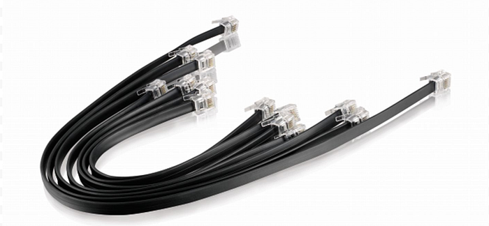
- Come in varying lengths
* Running Torque = torque required to keep the shaft rotating at constant angular velocity [8]
** Stalling Torque = maximum torque that can be applied to make the motor stop rotating [8]
Physical Changes
Transitioning from the initial prototype to the final cart was a lengthy process, but one that elucidated many misconceptions regarding the physical aspects of the mechanical system.
Motor Placement
At first, only one large motor was used to move the cart. Another was added, connected to the same axle on the front set of wheels, to provide more torque and greater stability/weight to the cart.
Gear Ratio
Initially, under the rationale that there would be a delay between the motor and wheel motion, the two large motors were connected directly to the wheels. However, the motors made by LEGO simply did not have enough speed in order to provide significant acceleration to the cart. A 3:1 gear ratio was implemented between the wheels and the motor in order to allow for the exertion of a greater force (resulting from greater acceleration), enabling stability for wider range of the pendulum positions.
Rod Sturdiness
The rod of the system was initially constructed purely of LEGOs. However, when the cart was moved back and forth, the rod wobbled significantly, vibrating back and forth and incorrectly fluctuating the readings of the gyroscopic sensor. To address this issue, a wooden rod was used, with holes drilled into either end of the stick to connect it firmly to both the cart and gyroscope.
Rod Center of Mass
At first, all that was attached to the rod was simply a gyroscopic sensor at the very end. Yet this placement, although shifting it slightly upwards, barely moved the center of mass of the rod away from its halfway point. As gleaned from the equations of motion (discussed below), having a center of mass further from the hinge on the cart entails the need for less torque to balance the rod. A similar situation can be seen in the analogy of pushing a door open. When pushing near the hinge, even though the distance traveled by one’s hand is less, the force that individual has to exert is significantly greater. In contrast, when pushing near the handle, less force is needed to move the door by the same angle. This is because torque applied for rotational motion is equal to the perpendicular force multiplied by the distance from the axis of rotation [8].
Rod Length
The length of the rod was a factor that was not paid much attention to during the construction process. It was incorrectly assumed that a longer rod would be harder to control and balance. Yet the equations of motion (discussed below) revealed that a longer pendulum required less force to keep upright. Manual attempts to balance both a short and a long stick confirmed this.
Usage of Medium Motor/Encoder
Many of the research papers dealing with a similar topic utilized two different means of measuring the angle of the rod: the usage of a motor and the usage of a gyroscope. Initially, a medium motor was mounted on the cart and attached to the pendulum on its axle of rotation. However, the measured angle by the motor on the motor was somewhat inaccurate due to some looseness in the rotor. Therefore, the LEGO Gyroscopic sensor was utilized.
Mounting of Gyroscope
LEGO cables were used to connect the gyroscopic sensor to the EV3 Brick. Initially, under the misconception that a longer cable would entail a higher latency between the sensor reading and the motion of the motor, the gyroscope was mounted close to the base of the rod, with the shortest LEGO cable used to connect it to the brick. However, this position did not allow for much precision. Instead, the gyroscope was moved to be placed at the very top of the rod. Such a change allowed for a greater degree of exactitude with a negligible tradeoff in latency.
Final Cart and Pendulum
After many iterations and revisions, the following inverted pendulum system was finalized and programmed in an attempt to balance the rod in a vertical position.
The above four images show the cart itself, capturing the following four components:
- Red accelerometer (placed above the front two wheels)
- EV3 Programmable Brick (mounted towards the rear of the robot)
- Large motors (the white drum-shaped piece visible in [D] between the two wheels)
- Cables used to connect these components together (both grey and black)
The 3:1 gear ratio, circled in red, and the gyroscopic sensor, mounted at the end of the pendulum, can be seen in the below images [E] and [F] respectively:
The specifications of this finalized mechanical system are detailed in the following table.
Mass of System — 1.5 kg
Mass of Pendulum — 0.1 kg
Mass of Cart — 1.4 kg
Length of Pendulum — 1.22 m
Distance from hinge to rod center of mass — 1.01 m
Derivation of the Equations of Motion
Once the physical system was completed, to begin programming, the equations of motion for the system needed to be derived. Two free-body diagrams were constructed.
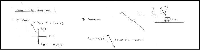
The following three initial equations of motion were drawn. There is no equation written for the cart in the ĵ direction as the cart does not move vertically, only horizontally [9].
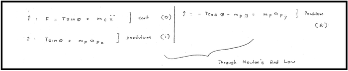
These three initial equations of motion were rewritten and simplified (by eliminating T).
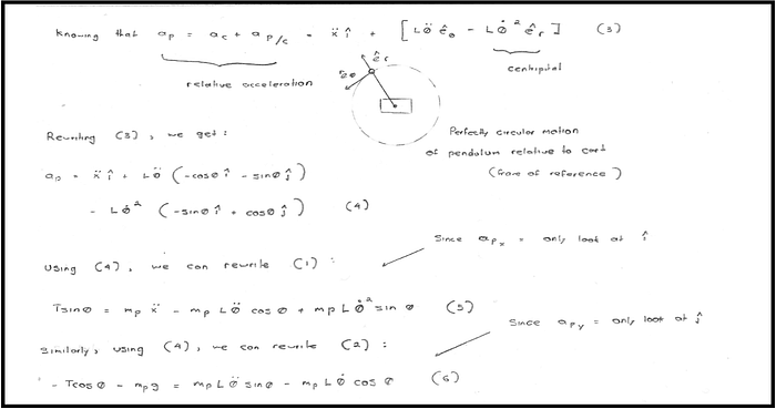
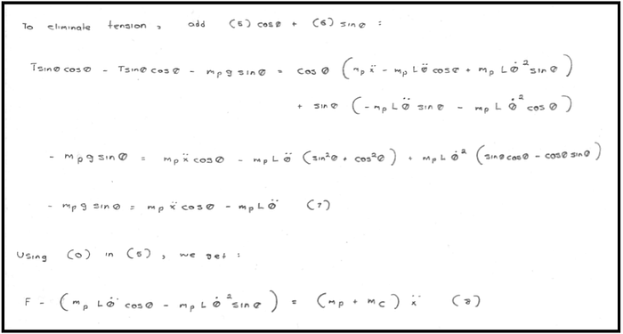
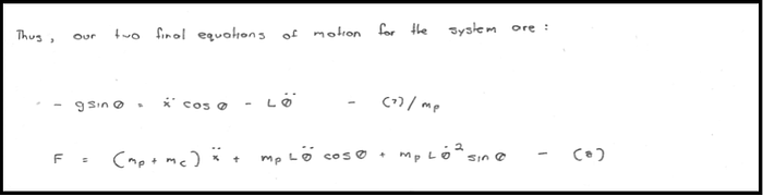
The resulting two equations of motion illustrate the relationships between the force F exerted on the cart, the mass mC of the cart, the mass mP of the pendulum, the acceleration d²x/dt² of the cart, the length L of the pendulum, the angular acceleration d²θ/dt², the angular velocity dθ/dt, and the angle θ of the rod [9].
Analysis of the Obtained Equations
These equations of motion are nonlinear due to the presence of sinθ and cosθ. One methodology to account for this is to let sinθ be equal to θ for angles between -15 and 15 degrees[10]. However, such a limited range illustrates the unstable nature of the system. In addition, solving the two differential equations will require the use of topics which are beyond the scope of this class: transfer functions, state-space equations, and the Simulink software package [11]. In addition, these equations only function in ideal conditions, ignoring factors such as friction and air resistance [9]. Although the equations of motion reveal relationships between the force applied to the cart and the movement of the pendulum, they are insufficient in providing a stabilizing control. The usage of control theory is required for deriving a mechanism to control this nonlinear system [15].
Using Proportional-Integral-Derivative (PID) Control
Introduction to PID Control
Proportional-Integral-Derivative, or PID, control is one methodology that can be used to control the motion of the inverted pendulum. The controller works as follows:
Based on an inputted target value, three measurements are calculated:
- ε — the current error (proportional)
- Δε — the summation of error (integral)
- dε — the rate of change of error (derivative)
These three measurements are added together, multiplied first by different, fixed gain factors kP, kI, and kD respectively
- Sum = (kP ✕ ε ) + (kI ✕ Δε ) + (kD ✕ dε )
This aggregate error is used to correct the system until the error reaches zero (at which point, the system will no longer change since the feedback will also be zero)
The constants kP, kI, kD, and the sampling rate, or the rate at which calculations and their ensuing adjustments are made, can be adjusted and will differ for each system. Although there exist several methods to mathematically determine the exact values of these factors which will lead to the stability of a system, these methods involve advanced mathematical concepts (transfer functions, state-space equations) and the usage of modelling software such as Simulink [11].
Implementing PID Control using LEGO Mindstorms EV3 Software
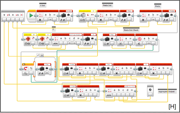
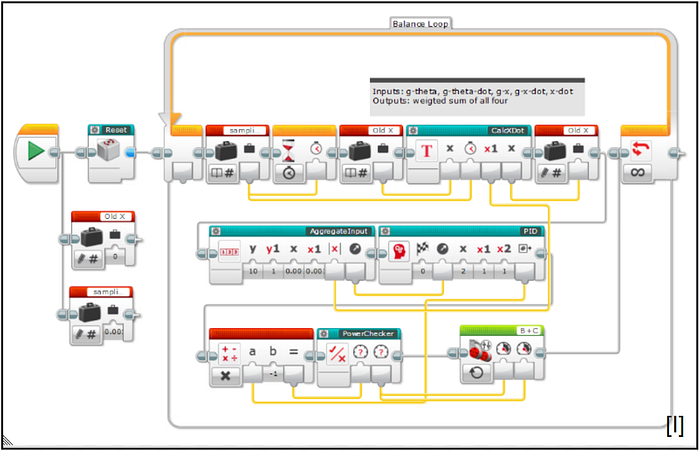
To program the system, LEGO MINDSTORMS EV3 software was used. First, the PID control feedback loop itself was implemented [G]. Next, as revealed from our equations of motion, the current position of the cart, the velocity of the cart, the angular position of the pendulum, and the angular velocity of the pendulum are needed for calculating the force to be applied on the cart. An aggregate input was determined using the four input variables X, dX/dt, θ, and dθ/dt, each multiplied by a distinct gain factor, which was also determined through manual experiments [H]. Putting both of these components in an infinite loop, with the output of the aggregate input feeding into the PID control and the output of the PID control feeding into the motors of the cart, our feedback-control system for the cart was completed [I]. All that remained was the finding of the values of the four gain factors and the three constants kP, kI, and kD.

Tuning the System
In order to determine the appropriate values of these constants, manual tuning of the system was required. The following guidance table, created by researchers at Purdue University, was used in finding kP, kI, and kD [12].
The table* above provides details regarding the changes that increasing kP, kI, and kD bring to the following four characteristics of the mechanical system:
- Rise time (this factor bears no significance for the LEGO pendulum since it its starting position is upright as the motors simply lack the torque for a swing up)
- Overshoot (swinging the rod past the target angle of 0 degrees)
- Settling time (time taken for the rod to stabilize at the target angle)
- Steady State Error (the movement of the cart at the rod’s stable position)
* Where NT means No Trend present when the value of the respective k is increased [12]
However, despite over many hours of adjustment and iterations in both the physical system and the values of the gain factors and kP, kI, and kD, a stable control for the system was unable to be obtained. Finding these factors by experimentation takes a substantial amount of time. It is possible that by spending more time tuning, appropriate values of the seven constants in total would be determined. Additionally, if transfer functions, state- space equations, and Simulink were used, kP, kI, and kD could be calculated accurately [16].
The physical limitations of the LEGO components may be playing a role as well. The motors used simply did not have enough torque and precision to move the cart with sufficient exactitude. The gyroscopic sensor, as listed on the LEGO website, boasted merely an accuracy within +/- 3o. In addition, the friction on the hinge connecting the rod and cart and between the wheels and the ground was unaccounted for.
Such limitations prevented the system from stabilizing, only being able to balance the rod for a few seconds at a time. Other projects involving LEGO MINDSTORMS EV3 employed a custom GlideWheel-M multifunctional sensor and accompanying Simulink packages in order to successfully control the cart [14]. Yet as of now, this sensor is still out of stock.
Conclusion and Applications
This project was conducted with the goal of creating a functional inverted pendulum using a LEGO MINDSTORMS EV3 kit. Although the mechanical system did not stabilize due primarily to the physical limitations, time frame, and nonlinear nature of its motion, the process provided insight into the relationship between the force exerted on the cart and the motion of the pendulum. The simplified equations of motion, shown below,
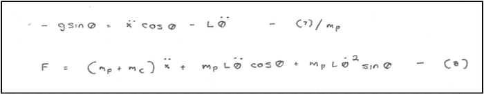
cannot be solved using the knowledge attained in the first trimester of Post-AP Differential Equations. Other endeavors in this field have utilized tools such as transfer functions, state-space equations, and powerful software such as Simulink and MATLAB [16]. Given more time and more capable physical components (including more accurate gyroscopic sensors [14]), however, the PID control could be tuned to provide stability to the system.
The difficulty in creating and programming such a system stemmed from its physical, mechanical nature. The environmental conditions of its motion were less than ideal, with many factors such as friction and latency being unaccounted for. Regardless, several misconceptions and relations were elucidated through this project, ranging from the length of the rod to the components needed to determine the force exerted at any given instant.
The classic inverted pendulum problem bears great significance in both the study of control theory and the development of new technologies involving stability. The study of this mechanical system allows for a connection between theory and application [1].
References
- Kafetzis, Ioannis, and Lazaros Moysis. Inverted Pendulum: A System with Innumerable Applications. School of Mathematical Sciences, Aristotle University of Thessaloniki, Mar. 2017.
- “EV3 Intelligent Brick 45500: MINDSTORMS®: Buy Online at the Official LEGO® Shop US.” 45500 | MINDSTORMS® | Buy Online at the Official LEGO® Shop US, 18 Aug. 2019, www.lego.com/en-us/product/ev3-intelligent-brick-45500.
- “EV3 Large Servo Motor 45502: MINDSTORMS®: Buy Online at the Official LEGO® Shop US.” 45502 | MINDSTORMS® | Buy Online at the Official LEGO® Shop US, 28 Aug. 2019, www.lego.com/en-us/product/ev3-large-servo-motor-45502.
- “EV3 Medium Servo Motor 45503: MINDSTORMS®: Buy Online at the Official LEGO® Shop US.” 45503 | MINDSTORMS® | Buy Online at the Official LEGO® Shop US, 6 Sept. 2019, www.lego.com/en-us/product/ev3-medium-servo-motor-45503.
- “EV3 Gyro Sensor 45505: MINDSTORMS®: Buy Online at the Official LEGO® Shop US.” 45505 | MINDSTORMS® | Buy Online at the Official LEGO® Shop US, 19 Oct. 2019, www.lego.com/en-us/product/ev3-gyro-sensor-45505.
- “Gyro, MultiSensitivity Accelerometer and Compass for NXT or EV3.” Mindsensors.com, www.mindsensors.com/ev3-and-nxt/15-gyro-multisensitivity-accelerometer-and-compass-for-nxt-or-ev3.
- “EV3 Cable Pack 45514: MINDSTORMS®: Buy Online at the Official LEGO® Shop US.” 45514 | MINDSTORMS® | Buy Online at the Official LEGO® Shop US, www.lego.com/en-us/product/ev3-cable-pack-45514.
- Takasaki, Bruce. “The Basics of Torque Testing.” Quality Magazine RSS, Quality Magazine, 14 Sept. 2012, www.qualitymag.com/articles/87967-the-basics-of-torque-testing.
- Coller, Brianno, director. Classic Inverted Pendulum — Equations of Motion . YouTube, YouTube, 18 Mar. 2015, www.youtube.com/watch?v=5qJY-ZaKSic.
- Controlling the Inverted Pendulum. Example of a Digital Feedback Control System., daviddeley.com/pendulum/pendulum.htm#page1a.
- “Inverted Pendulum: System Modeling.” Control Tutorials for MATLAB and Simulink — Inverted Pendulum: System Modeling, ctms.engin.umich.edu/CTMS/index.php?example=InvertedPendulum§ion=SystemModeling.
- Zhong, Jinghua. PDF Controller Tuning: A Short Tutorial. Purdue University, 2006.
- Witzand, Steven J. Coordinate LEGO Segways. The University of New South Wales , Nov. 2009.
- Masakakatsukawata, director. Inverted Pendulum on a Cart (LEGO MINDSTORMS EV3). Youtube , Dec. 2014, www.youtube.com/watch?v=vQ607X6Rid4.
- Xu, Xu, et al. Case Studies on Nonlinear Control Theory of the Inverted Pendulum.
- Mbuthia, M., and P. Musau. Design and Implementation of a Digital Controller for a Walking Robot Using LEGO Components . University of Nairobi, 24 Apr. 2015.